 FLECONN M5 M8 M12 M16 M23 Connector and Cable Assembly, Custom Overmolded Cable Assemblies, Wire Harness Manufacturer
 Product Categories
Contact detail
- Mobile Phone:+86 13265562978
- Tel:+86 755-23490966
- Email:sales@fleconn-china.com
Chat Now:


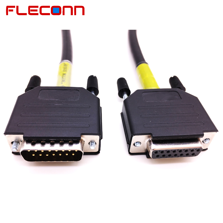





DB15 Male to Female Cable, Connector with Plastic Assembly Backshell
E1005
DB15 Male to Female Cable, D-sub 15 pin Male to Female Connector Cable, Male D-sub 15 way to Female DB9 Extension Cable
FLECONN can custom db15 male to female cable, d-sub connector with plastic assembly backshell for industry equipment manufacturers.
Product Description
DB15 Male to Female Cable, Connector with Plastic Assembly Backshell
FLECONN can custom db15 male to female cable, d-sub connector with plastic assembly backshell for industry equipment manufacturers.
DB15 male to female connector cable assembly process
1 Cable assembly Parts
1.1 Cable
1. 15 core or greater 24AWG MINIMUM 10 STRANDS shielded, 350mm long
OR
2. 6-core 24AWG MINIMUM 10 STRANDS shielded, two lengths of 350mm to meet core count
required.
MULTICOMP SPC19822-RH (Element14 1846734) or equivalent
1.2 Termination J9 Parts (Electronics)
1. D Sub, DA, Plug, 15-way Solder
MULTICOMP 5501-15PA-02-F1 (Element14 108467301) or equivalent.
2. D Sub, DA, Backshell; Black, Nylon with manual screws
MULTICOMP MC-DPPK15-K (Element14 2346823) or equivalent.
1.3 Termination J10 Parts (Camera)
1. D Sub, DA, Receptacle, 15-way, Solder
FCI DA15S064TLF (Element14 2112356) or equivalent.
2. D Sub, DA, Backshell; Black, Nylon with manual screws
MULTICOMP MC-DPPK15-K (Element14 2346823) or equivalent
2 Assembly
2.1 Assembly J9
. Strip outer sleeve approx. 25mm.
. Twist drain/shield together.
. Strip cores wires over 2mm.
. Twist core wire ends.
. Add label “BOTTOM SENSOR” onto cable and cover with clear heatshrink.
. Solder core wires into D-sub solder cups.
. Put D-sub into shell.
. Attach strain relief. Ensure strain relief is applied on cable outer sleeve.
. Complete shell assembly with manual screws.
2.2 Assembly J10
. Strip outer sleeve approx. 25mm.
. Twist drain/shield together.
. Strip cores wires over 2mm.
. Twist core wire ends.
. Add label “BOTTOM SENSOR” onto cable and cover with clear heatshrink.
. Solder core wires into D-sub solder cups.
. Put D-sub into shell.
. Attach strain relief. Ensure strain relief is applied on cable outer sleeve.
. Complete shell assembly with manual screws.
3. D-sub 15 Pin male to female connector wire connection diagram

Send Inquiry Now!
* Relative Products & DB15 Male to Female Cable, Connector with Plastic Assembly Backshell


- The connector
- Electrical Connectors
- Wire-to-Wire Connector
- Wire-to-Board Connector
- Board-to-Board Connector
- I/O USB Connectors
- M8 M12 connector
- M8 Field Wireable Connector
- M8 Panel Mount Connectors
- M8 Cable Assembly
- M12 connector
- M12 Connectors, Field Wireable
- M12 Panel Mount Connectors
- M12 X Coding Connector
- Other products
- Custom Cable Assembly
- Wire Harness Manufacturer
- Cable/ Wiring Loom Manufacturer
- Custom USB cables
- Custom Waterproof Cable
- Custom HDMI Cables
- M5 Connector/ M5 cable
- M8 Connector
- M12 Cable Assembly
- Product Design Services
- Custom Connector Developing
